3D Programming: Part 2
In the first part, I explained how to manage, project and display single points in 3D. In this part, I will show how to deal with lines, surfaces and solid objects made up of collections of surfaces.
I. Lines
A line is defined by the two points that mark its ends, or equivalently by an endpoint, a direction vector and a length. (Strictly speaking, in mathematical terms this is a line segment, but full or half lines are not often useful.).
Projection: With most views, a line which lies entirely within the visible region can be projected simply by projecting the endpoints and drawing a line in 2D with enough accuracy to be acceptable. However, if a line has one or both ends outside the visible region, you need to bring that end (or both ends) in towards the other until it is visible before projecting.
For a small field of view, you can assume that the visible region is y>0 in camera space (i.e. everything forward of the camera), which makes it easy to bring the endpoints in. Simply use linear interpolation on y (if both points are behind the camera, the whole line is invisible, so just don't project it at all). Because you're defining your visible region in terms of a single plane, you don't have to worry about a line which has both endpoints outside the region but a part of it within.
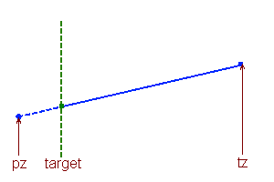
Interpolating a new endpoint on a line based on a coordinate threshold. The original left endpoint is the wrong side of the target value, and a new endpoint (green) is calculated by moving up the line towards the right endpoint by a factor (target-pz)÷(tz-pz).
As shown in this diagram, the new endpoint P1 to replace an out-of-range endpoint p1 is:
P1 = p1 + (p2-p1)ū(target-p1y)÷(p2y-p1y)
If the threshold plane is not along an axis, you need to use p1.n and p2.n for pz and tz and r.n for target, where n is the plane normal and r is any point on the plane (–r.n is often stored as part of the plane definition).
Rendering: Because projection can give very large 2D coordinates for some 'visible' points, you may have trouble rendering the projected lines in some environments. (SVG, PDF and Flash, for example, all have trouble with very large coordinates.) So once again, use interpolation along the line to bring the endpoints back to a smaller coordinate near the viewport. You can do it in X and Y independently as the combined space is more restricted than either individually. (In fact this is a general property of restricted convex spaces, so if your 3D visible region is a convex polyhedron, you can use interpolation on any faces which an endpoint is outside in any order to clip lines to it.)
Useful operations. Lines and points don't collide (except in a few carefully arranged special cases), but there are a few ways in which you might want to use lines and points in your simulation.
- Point-line closest approach: to find the point on a line segment (p1 to p2) that is the closest to another point (q) in space. First, find how far along the line the point will be: f = [(q-p1).(p2-p1)]÷|p2-p1|▓. If f is less than zero, then q is off the 'beginning' of the line and the closest point is p1; likewise, if f>1, the closest point is p2. Otherwise, q is alongside the line segment and the closest point is p1+f(p2-p1).
- Line-line closest approach: to find the closest point between two line segments [p1,p2] and [q1,q2]. Unfortunately this problem is not as trivial as it may appear, and a full explanation is more than would fit here, but this excellent article explains how to find this and other related properties.
II. Surfaces
A surface, or face, is a section of a plane, defined by the points which bound it. In many cases it will be a triangle, which has the advantage that any triangle forms part of a single plane, and an incorrectly specified face with more sides may not do so (and will therefore render strangely from some angles. If you choose to allow faces with more sides (and it can be convenient to do so), you should make sure that the points are all coplanar.
Projection: As with lines, you may need to clip a shape to the projectable region. However, with a polygon, you may have to alter the number of points as you add new line segments or remove those which are entirely outside the projectable region.
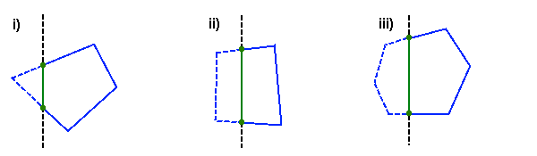
A shape clipped to a threshold plane with (i) one, (ii) two or (iii) several consecutive points outside the region. The two green vertices and the green line replace the dashed blue line segments and vertices in each case.
When clipping a face, you always generate two new vertices and one new edge, and you remove all vertices and edges which are entirely beyond the threshold plane. (As with lines, if your projectable region has several bounding planes, you can clip to each one in turn as long as the space is convex.) This means that when only one vertex is outside, the resulting clipped face has one extra vertex; when two are outside, the same number; and when several are outside, less.
Here's my code for clipping a surface – note that I'm checking the Z coordinate of the projected points in the test. If you're not using a simple 1/z projection, you should do this test on the 3D points, before projection, in the camera's local space instead.
var tz:Number = p.threshold * 2;
var needsAdjust:Boolean = false;
for (var i:int = 0; i < projPoints.length; i++) {
	if (!projPoints[i]) return;
	if (projPoints[i].z <= tz) { needsAdjust = true; break; }
}
if (needsAdjust) {
	var newProjPoints: Vector.<Vector3> = new Vector.<Vector3>();
	for (i = 0; i < projPoints.length; i++) {
		var point:Vector3 = projPoints[i];
		if (point.z <= tz) {
			// If a projected point is behind the Z axis, we may need to create a new point and interpolate
			// towards the adjacent points in real 3-space
			var prev:Vector3 = projPoints[(i + projPoints.length - 1) % projPoints.length];
			var next:Vector3 = projPoints[(i + 1) % projPoints.length];
			if (prev && (prev.z > tz)) {
				var tprev:Vector3 = tp[(i + tp.length - 1) % tp.length];
				var ip:Vector3 = MoveTowards(tp[i], tprev, point.z, prev.z, tz);
				if(ip) newProjPoints.push(p.Project(ip));
			}
			if (next && (next.z > tz)) {
				var tnext:Vector3 = tp[(i + 1) % tp.length];
				ip = MoveTowards(tp[i], tnext, point.z, next.z, tz);
				if(ip) newProjPoints.push(p.Project(ip));
			}
		} else newProjPoints.push(point);
	}
	if (newProjPoints.length == 0) return;
	projPoints = newProjPoints;
}
Rendering: As with lines, you may have trouble rendering a surface which extends to very large projected coordinates, and you may need to clip the projected shape in a similar way to the clipping on the original shape needed before projecting.
Facing direction: A good optimisation which is covered in almost every 3D graphics engine is to not draw surfaces which are facing away from the camera (because in a solid object, they will be hidden). This algorithm is simple: if the normal of the surface is pointing in the same direction as the vector from the camera to the surface, don't draw it.
The normal of a face can be defined in two ways, depending on which way around the vertex vector you go. The two options (clockwise and anti-clockwise winding, i.e. on a visible face, the vertices are indexed in a clockwise or anti-clockwise fashion) are equally valid, and you should simply choose one. I use (v1-v0)ū(v2-v0) which gives an anti-clockwise winding rule; do the cross product the other way around for a clockwise one.
III. Solid Objects
A solid object is simply a collection of vertices and faces which share a common transformation matrix. To project and render an object, simply project and render each face in turn, making sure that your renderer sorts all the lines, points and surfaces it is supposed to be drawing correctly.
IV. Diffuse and Ambient Lighting
One thing that really makes a 3D scene work is lighting. There are various advanced techniques that you can use to vary light levels across a face, but in this article I will just show you how to add flat lighting (i.e. a single light level) to a face. This will give your games or graphics a rather retro feel, but it will serve to enhance the 3D, and if you want to use more advanced techniques then you will almost certainly be using a graphics card accelerated library which will do them for you automatically.
Light is usually thought of in terms of a factor, from 0 to 1, which is used to multiply the base colour of an object (possibly three factors for each of the colour channels) to produce a rendered colour which is darker than the base colour. This means that you can never 'white out' a face by shining a light on it, and also that black surfaces will always remain black. In essence, diffuse and ambient lighting model a completely matt surface.
Ambient light is simply the minimum level at which all objects within the scene are lit if they are not lit by any particular sources. If this is set to zero then faces in 'shadow' will be completely black, and it will be difficult to pick out the shape of objects. Setting it too high means that light sources do not have an obvious effect on your scene, which can also make it look flat.
Diffuse light is that caused by a light shining onto a surface and scattering in all directions, lighting it evenly. A simple formula for a diffuse lighting factor is:
f = (k÷|l-p|)▓(n.norm(l-p)), clamped to [0,1]
... where n is the normal of the surface being lit, p is its origin, l is the location of the light and k is a constant depending on the strength of the light (the range at which faces are fully lit if they face the light). (If you are writing a shader that will create a lightmap for the surface, instead of picking a single p, vary p across the surface to calculate the light at each point on it.)
You can either clamp the whole expression, which will cause objects close to a light to be fully lit even on their surfaces at shallow angles to it (making them appear flat), or clamp (k÷|l-p|), which will result in objects close to a light but at a low angle to it being lit according to the angle, as if they were k units away (making the light appear less strong).
If there are multiple light sources, you can simply add the factors together, making sure that the eventual lighting factor (ambient+Σ[diffuse sources]) is clamped to [0,1]. If you want to have coloured lights, you can allow each light to have a different k-factor for each of the three colour channels.
V. Specular Lighting
The third type of lighting, specular, is light which is reflected off the surface; that is, the specular light level of a point or surface depends on where you are viewing it from. The strength of a specular light depends on the distance of the light source and how close to a perfect reflection angle it is being viewed from. To calculate it, we use the fact that a reflection can be 'undone' by moving a point to the other side of the reflection plane through the origin by r' = r-2n(r.n), with n being the plane normal.
So, to find the level of specular light from one light source, use:
c = k([L-2n(L.n)].V - [1 - (1/k)])
L = norm(l-p)
V = norm(v-p)
... with l being the location of the light, v the viewpoint, n the plane normal, p a point in the plane (so l-p and v-p are the local coordinates of the light and the viewpoint) and k a factor relating to the maximum specular angle for this light. A k factor of 2 shows specular highlights up to 60░ from the perfect reflection angle (where the dot product is Į); in general, k = 1/cos a where a is the maximum angle at which a specular highlight will be generated. If the light is on the correct side of the face, c will be in the range 0-1.
Typically you will then want to scale c by some function of the distance from the light to the observer (1/[|l-p|+|v-p|]▓ is common). You can sum multiple lights by adding together their c-factors, clamping the total to [0,1]. A surface typically has a different specular colour to its ambient/diffuse colour, often white, allowing a specular light to change the rendering of the surface to colours which are not possible with diffuse lighting.
As before, for flat shading p will be the face origin, and for smooth shading p will vary across the surface.